 https://silvaco.com/wp-content/uploads/2020/10/simstd_Q3_2020_hints.jpg
719
554
Erick Castellon
/wp-content/uploads/2019/11/silvaco-logo.png
Erick Castellon2020-10-01 00:02:522021-07-16 21:32:09Using Victory Process Open Model Interface to Customize Etch Emulation Model – Example
https://silvaco.com/wp-content/uploads/2020/10/simstd_Q3_2020_hints.jpg
719
554
Erick Castellon
/wp-content/uploads/2019/11/silvaco-logo.png
Erick Castellon2020-10-01 00:02:522021-07-16 21:32:09Using Victory Process Open Model Interface to Customize Etch Emulation Model – Example https://silvaco.com/wp-content/uploads/2020/07/VP_Figure3b.png
889
966
Erick Castellon
/wp-content/uploads/2019/11/silvaco-logo.png
Erick Castellon2020-07-31 04:51:532021-07-16 21:32:102020 TCAD Baseline Release Section 1: Process Simulation – New Features in 2020 Baseline Release
https://silvaco.com/wp-content/uploads/2020/07/VP_Figure3b.png
889
966
Erick Castellon
/wp-content/uploads/2019/11/silvaco-logo.png
Erick Castellon2020-07-31 04:51:532021-07-16 21:32:102020 TCAD Baseline Release Section 1: Process Simulation – New Features in 2020 Baseline Release https://silvaco.com/wp-content/uploads/2020/07/Mesh_Figure3b.png
881
946
Erick Castellon
/wp-content/uploads/2019/11/silvaco-logo.png
Erick Castellon2020-07-31 04:34:592021-07-16 21:32:102020 TCAD Baseline Release Section 2: Meshing – New Features in 2020 Baseline Release
https://silvaco.com/wp-content/uploads/2020/07/Mesh_Figure3b.png
881
946
Erick Castellon
/wp-content/uploads/2019/11/silvaco-logo.png
Erick Castellon2020-07-31 04:34:592021-07-16 21:32:102020 TCAD Baseline Release Section 2: Meshing – New Features in 2020 Baseline Release https://silvaco.com/wp-content/uploads/2020/07/reram_fig1.png
1200
1600
Erick Castellon
/wp-content/uploads/2019/11/silvaco-logo.png
Erick Castellon2020-07-31 04:25:342021-07-16 21:32:112020 TCAD Baseline Release – Device Simulation – New Features in 2020 Baseline Release
https://silvaco.com/wp-content/uploads/2020/07/reram_fig1.png
1200
1600
Erick Castellon
/wp-content/uploads/2019/11/silvaco-logo.png
Erick Castellon2020-07-31 04:25:342021-07-16 21:32:112020 TCAD Baseline Release – Device Simulation – New Features in 2020 Baseline Release https://silvaco.com/wp-content/uploads/2020/03/q1-2020-a1-thumb.png
735
673
Graham Bell
/wp-content/uploads/2019/11/silvaco-logo.png
Graham Bell2020-03-03 17:57:272021-07-16 21:32:11Victory TCAD Suite: How to use it for fast, efficient, and accurate simulation of power semiconductor devices
https://silvaco.com/wp-content/uploads/2020/03/q1-2020-a1-thumb.png
735
673
Graham Bell
/wp-content/uploads/2019/11/silvaco-logo.png
Graham Bell2020-03-03 17:57:272021-07-16 21:32:11Victory TCAD Suite: How to use it for fast, efficient, and accurate simulation of power semiconductor devices https://silvaco.com/wp-content/uploads/2020/03/q1-2020-a2-thumb.png
455
553
Graham Bell
/wp-content/uploads/2019/11/silvaco-logo.png
Graham Bell2020-03-02 18:15:462021-07-16 21:32:25Hints and Tips: Specify Units in the Victory Process Material Statement
https://silvaco.com/wp-content/uploads/2020/03/q1-2020-a2-thumb.png
455
553
Graham Bell
/wp-content/uploads/2019/11/silvaco-logo.png
Graham Bell2020-03-02 18:15:462021-07-16 21:32:25Hints and Tips: Specify Units in the Victory Process Material Statement https://silvaco.com/wp-content/uploads/2020/03/q1-2020-a3-thumb.png
673
975
Graham Bell
/wp-content/uploads/2019/11/silvaco-logo.png
Graham Bell2020-03-01 18:28:582021-07-16 21:32:25Hints and Tips: How do I Load, Remesh, and Refine an Existing Device Structure in Victory Mesh?
https://silvaco.com/wp-content/uploads/2020/03/q1-2020-a3-thumb.png
673
975
Graham Bell
/wp-content/uploads/2019/11/silvaco-logo.png
Graham Bell2020-03-01 18:28:582021-07-16 21:32:25Hints and Tips: How do I Load, Remesh, and Refine an Existing Device Structure in Victory Mesh? https://silvaco.com/wp-content/uploads/2019/09/simstd_Q4_2019_a4-1.jpg
1012
782
Ingrid Schwarz
/wp-content/uploads/2019/11/silvaco-logo.png
Ingrid Schwarz2019-10-01 00:04:372021-07-16 21:32:26Maverick: Hierarchical Netlist Extractor for PC Platforms
https://silvaco.com/wp-content/uploads/2019/09/simstd_Q4_2019_a4-1.jpg
1012
782
Ingrid Schwarz
/wp-content/uploads/2019/11/silvaco-logo.png
Ingrid Schwarz2019-10-01 00:04:372021-07-16 21:32:26Maverick: Hierarchical Netlist Extractor for PC Platforms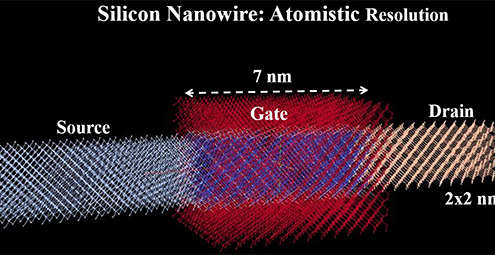 https://silvaco.com/wp-content/uploads/2019/09/PID6049157_fig3.jpg
255
550
Erick Castellon
/wp-content/uploads/2019/11/silvaco-logo.png
Erick Castellon2019-09-05 00:00:142021-07-16 21:32:26Next Generation CMOS Nanowire: From Atoms to Circuit Simulation
https://silvaco.com/wp-content/uploads/2019/09/PID6049157_fig3.jpg
255
550
Erick Castellon
/wp-content/uploads/2019/11/silvaco-logo.png
Erick Castellon2019-09-05 00:00:142021-07-16 21:32:26Next Generation CMOS Nanowire: From Atoms to Circuit Simulation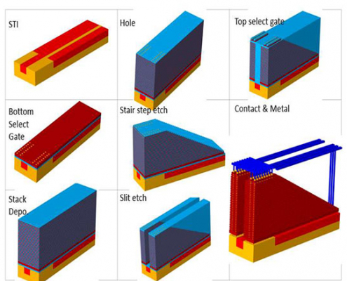 https://silvaco.com/wp-content/uploads/2019/09/sispad_fig1.jpg
439
550
Erick Castellon
/wp-content/uploads/2019/11/silvaco-logo.png
Erick Castellon2019-09-04 00:00:152021-07-16 21:32:27Optimization of Select Gate Transistor in Advanced 3D NAND Memory Cell
https://silvaco.com/wp-content/uploads/2019/09/sispad_fig1.jpg
439
550
Erick Castellon
/wp-content/uploads/2019/11/silvaco-logo.png
Erick Castellon2019-09-04 00:00:152021-07-16 21:32:27Optimization of Select Gate Transistor in Advanced 3D NAND Memory Cell