New Parasitic Capacitance Modeling in Hipex-C
Introduction
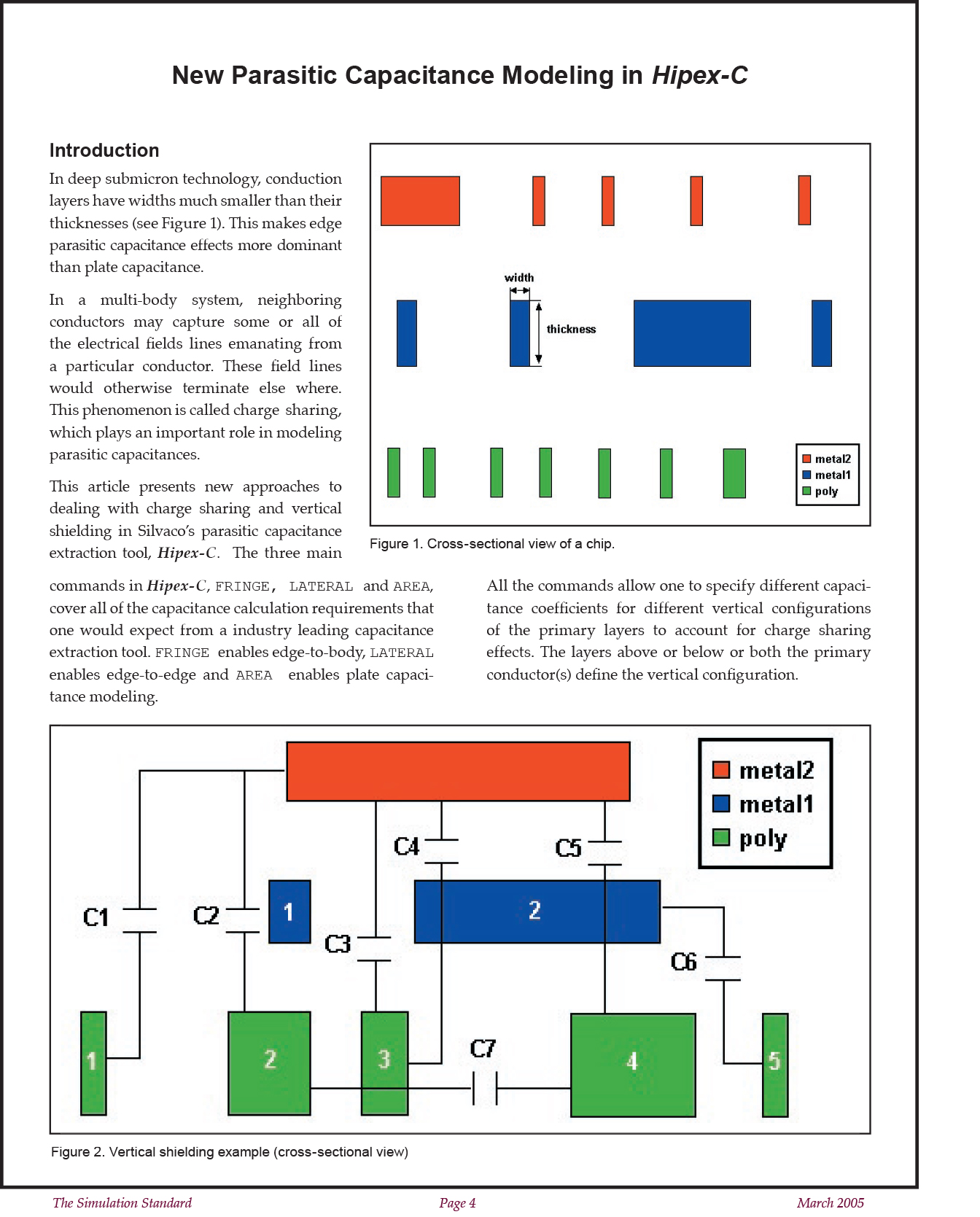
In deep submicron technology, conduction layers have widths much smaller than their thicknesses (see Figure 1). This makes edge parasitic capacitance effects more dominant than plate capacitance.
In a multi-body system, neighboring conductors may capture some or all of the electrical fields lines emanating from a particular conductor. These field lines would otherwise terminate else where. This phenomenon is called charge sharing, which plays an important role in modeling parasitic capacitances.
This article presents new approaches to dealing with charge sharing and vertical shielding in Silvaco’s parasitic capacitance extraction tool, Hipex-C. The three main commands in Hipex-C, FRINGE, LATERAL and AREA, cover all of the capacitance calculation requirements that one would expect from a industry leading capacitance extraction tool. FRINGE enables edge-to-body, LATERAL enables edge-to-edge and AREA enables plate capacitance modeling.
All the commands allow one to specify different capacitance coefficients for different vertical configurations of the primary layers to account for charge sharing effects. The layers above or below or both the primary conductor(s) define the vertical configuration.
Vertical Shielding
Vertical shielding is caused by the vertical order of layers. When more than two conduction layers overlap, the inside layers shield the capacitance effects between the outer layers, Figure 2. demonstrates the effects of vertical shielding.
Note the following vertical shielding effects for primary layers metal2 and poly:
- The first metal1 shape is shielding the metal2 edge from the edge of the first poly shape (lateral C1) and the body of the second poly shape (fringe C2)
- The second metal1 shape is shielding the edge of the third poly shape from the metal2 body (fringe C4) and the bodies of the metal2 shape and the fourth poly shape from each other (area C5)
For lateral capacitance, a primary layer shape can shield another primary layer shape:
- The third poly shape is shielding the edges of the second and fourth poly shapes from each other (lateral C7)
- The fourth poly shape is shielding the metal1 edge from the edge of the fifth poly shape (lateral C6)


