Mixed Mode Radiation Event Detector
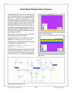
A reversed biased PIN diode acts as a radiation event detector, sensing the occurrence of an ionizing radiation pulse, which is connected to a threshold detector, the resistor RThreshold, that drives the base input of a complementary (Q1 and Q2) pulse amplifier. The output of the amplifier is supplied to the base of Q4 that drives a pulse circuit (Q5 and Q6) with a time constant set by RT x CT. The Radiation Event Detector circuit is shown in Figure 1.
The PIN diode structure is generated using Victory Process. Since the PIN diode is cylindrically symmetric, one can use 2D Victory Process to generate the PIN diode structure, as shown in Figure 2 A and B.
This structure once generated can now be called from a mixed mode simulation as shown below:
ADIODE PWR15V=cathode PIN_NEG=anode GUARD_RING=pgate infile=pin_3D.str cylindrical
The generated user defined ionizing pulse is done using the combination of statements below:
.RAD PWL 0 0 0.9e-06 0 1.0e-06 1.0 2.0e-06 1.0 2.1e-06 0.0
The .RAD statements generates a piece-wise linear pulse at 0.9us with a rise time of 0.1us to a value of 1, with a width of 1us and then a fall time of 0.1us starting at 2us to a value of 0 at 2.1us. This .RAD pulse generations electron-hole pairs using the radiation statement as described in chapter 4 of the Victory Device manual.


