Hints, Tips and Solutions&May 2005
Q. I am currently using ATLAS/ Blaze to model the electrical properties of an LED device that I am investigating. Is it possible to examine the reverse ray trace from my simulated structure so that I can examine the angular distribution properties of the optical output of the device?
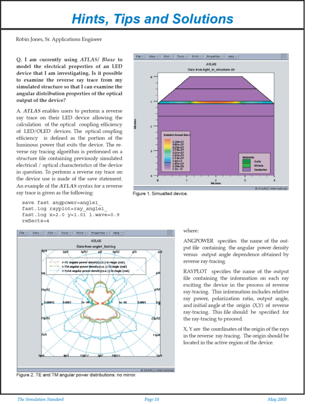
A. ATLAS enables users to perform a reverse ray trace on their LED device allowing the calculation of the optical coupling efficiency of LED/OLED devices. The optical coupling efficiency is defined as the portion of the luminous power that exits the device. The reverse ray tracing algorithm is performed on a structure file containing previously simulated electrical / optical characteristics of the device in question. To perform a reverse ray trace on the device use is made of the save statement. An example of the ATLAS syntax for a reverse ray trace is given as the following:
save fast angpower=angle1_fast.log rayplot=ray_angle1_fast.log x=2.0 y=1.01 l.wave=0.9 reflects=4
where:
ANGPOWER specifies the name of the output file containing the angular power density versus output angle dependence obtained by reverse ray-tracing.
RAYPLOT specifies the name of the output file containing the information on each ray exciting the device in the process of reverse ray-tracing. This information includes relative ray power, polarization ratio, output angle, and initial angle at the origin (X,Y) of reverse ray-tracing. This file should be specified for the ray-tracing to proceed.
X, Y are the coordinates of the origin of the rays in the reverse ray-tracing. The origin should be located in the active region of the device.L.WAVE is the wavelength of output radiation (needed for using appropriate refractive indexes of the materials). Should be specified for the ray-tracing to proceed.
In the above syntax readers will also notice the keyword fast. This is a new addition to the reverse ray tracing algorithm in Atlas that significantly increases the speed of the computation.


